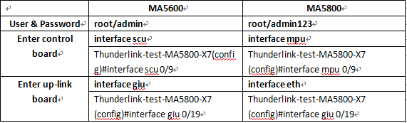
To set the port on the control board to the uplink port, run the electro-switch 0 location-0 command.
To set the port on the upstream interface board to the uplink port, run the electro-switch 0 location-1 command.
The Huawei SCUN control board can work with the upstream interface board at the same time. In this case, the SCUN control board equals an upstream board in another upstream interface board slot.
What’s the difference between Huawei S6720-32C-EI-24S-AC and S6720-30C-EI-24S Regarging the specification of ports?
Huawei S6720-32C-SI-AC supports 24*100M/1G/2.5G/5G/10G Base-T Ethernet ports, while Huawei S6720-30C-EI-24S supports 24*10GE SFP+ optical ports.
What Are the Differences Between the E Series, F Series, and S Series LPUs of the S7700&S9700?
Huawei Switch S7700 and Huawei Switch S9700 LPUs are classified into three series: E series, F series, and S series.
The E series is the enhanced series, and supports Multiprotocol Label Switching (MPLS) and extension of routing, ACL, and MAC address entries. The E series consists of the EA, EC, ED, and EE LPUs.
The F series is the ordinary series, and supports MPLS but not extension of MAC address entries. The F series consists of the FA and FC LPUs.
The S series is the standard series and does not support extension of MAC address entries. The S series consists of the SA and SC LPUs. The SA LPUs do not support MPLS, whereas the SC LPUs support MPLS.
![]() NOTE:
NOTE:
A, C, and D in the LPU names indicate the number of MAC address entries supported by the LPUs:
- A: 32K MAC addresses
- C: 128K MAC addresses
- D: 512K MAC addresses
Is There Any Limitation on the Slots of the Main Control Boards and LPUs On Huawei S7700/S9700?
Is There Any Limitation on the Slots of the Main Control Boards and LPUs On Huawei S7700/S9700 Switch?
A main control board can be installed in either of the two slots reserved for the main control board. An LPU can be installed in any slot reserved for LPUs. However, the main control board cannot be installed in the slot reserved for LPU, and the LPU cannot be installed in the slot reserved for the main control board.
What Switch model of Huawei support PoE?
If the model name of a switch contains PWR or PWH, this switch supports the PoE function. For example, S5700-24TP-PWR-SI is a PoE-capable switch.
What’s the difference between MA5683T and MA5800-X7?
The 40 Gbit/s-capacity Next-Generation Optical Line Terminal. Huawei’s SmartAX MA5800 multiple-service access module employs a distributed architecture to support ultra-broadband, Fixed Mobile Convergence services, and smart capabilities.
This article main talking about the difference between MA5683T & MA5800 X7 .
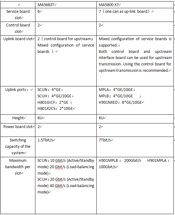
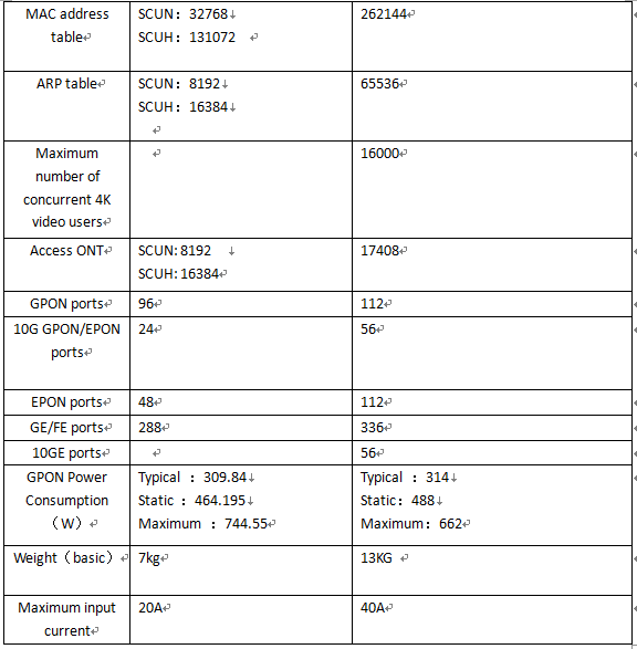
In addition to the basic performance of different, in the software system operation is also different, the following is the biggest difference.
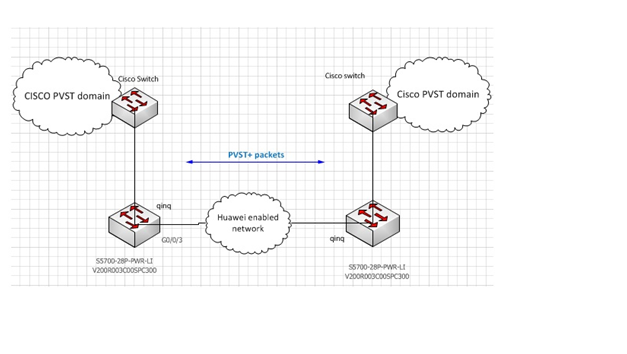
QinQ l2pt PVST+ failed because of miss-configuration
Issue Description
Topology:
Huawei S5700 related configuration:
Software Version V200R003C00SPC300
#
sysname Quidway
#
vlan batch 166
#
l2protocol-tunnel eoam3ah group-mac 0100-0ccd-
cdd0
l2protocol-tunnel gmrp group-mac 0180-e500-0001
l2protocol-tunnel gvrp group-mac 0180-e500-0002
l2protocol-tunnel cdp group-mac 0100-0ccd-cdd0
l2protocol-tunnel dtp group-mac 0100-0ccd-cdd0
l2protocol-tunnel pvst+ group-mac 0100-0ccd-cdd0
interface Vlanif1
ip address 10.10.2.41 255.255.255.0
#
interface GigabitEthernet0/0/1
port link-type trunk
undo port trunk allow-pass vlan 1
port trunk allow-pass vlan 166
stp disable
#
interface GigabitEthernet0/0/3
port link-type dot1q-tunnel
port default vlan 166
stp disable
l2protocol-tunnel stp cdp pvst+ enable
jumboframe enable 9712
#
PVST+ packets cannot pass through the tunnel and PVST domain cannot be integrated over Huawei network.
Alarm Information
<Quidway>display l2protocol-tunnel statistics GigabitEthernet 0/0/3
—————————————————————————–
Port Protocol Drop Input Output Drop
Threshold Packets Packets Packets
—————————————————————————–
GE0/0/3 stp 0 6 0 0
cdp 0 6 0 0
pvst+ 0 0 0 0
Statistic show only input packets. PVST+ packets cannot be transmitted properly.
Handling Process
By default, on V200R003 version, the packets with destination MAC address 0100-0ccc-cccc are processed as BPDUs, and packets with destination MAC address 0100-0ccc-cccd are forwarded by the hardware as data.
Because are forward as data packets, it will not be transmitted over layer 2 protocol tunnel. In this case we need to enforce the switch to process DA 0100-0ccc-cccd packets as bpdu and not as data packets.
Configuration:
<HUAWEI> system-view
[HUAWEI] bpdu mac-address 0100-0ccc-cccd
Root Cause
Capturing the packets on Gi0/0/3, relieved that packets are send through the tunnel without changing the destination address.
Since in the switch configuration we add “l2protocol-tunnel pvst+ group-mac 0100-0ccd-cdd0” command for l2protocol-tunnel group-mac definition, packets entering to the tunnel should have destination address, changed from “0100-0ccc-cccd” (default value) to “0100-0ccd-cdd0”.
Suggestions
Bridge protocol packets belonging to devices from other vendors need to be processed as BPDUs. You can set the MAC address of such packets to the MAC address of BPDUs
Services Are Interrupted Due to Different MTU Values on Huawei S5700 and Vendor R’s Switch
Issue Description
Two Huawei S5700s are configured in a stack. Each switch is connected to a vendor R’s switch through an Eth-Trunk that is aggregated by three Ethernet links. The 5700s, functioning as access switches, use Eth-Trunk interfaces to transparently transmit VLAN packets to vendor R’s switches. The gateway is configured on vendor R’s switch. Service interruption occurs from time to time, but the interface status is normal and no alarm information is generated. Such symptoms cannot be simulated.
Alarm Information
None
Handling Process
The MTU value on the S5700 cannot be changed. Therefore, change the MTU value on interfaces of vendor R’s switch to 1600. After the configuration, services are recovered.
Root Cause
When the fault occurs, capture packets on the S5700 and analyze the Eth-Trunk. It is found that the size of response packets is 1500 bytes or nearly 1500 bytes, and the DF value of these large packets is 1 indicating that the packets cannot be fragmented. Capture packets on the uplink device. It is found that the uplink device cannot receive large packets of 1500 bytes or nearly 1500 bytes. The fault may occur on the Eth-Trunk. After communication with vendor R, it is found that the MTU value is set to 1492 on member interfaces of the Eth-Trunk on vendor R’s switch. Change the MTU value to 1600. Services are recovered.
Suggestions
None
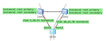
The port state in instance 2 of MSTP is not correct due to mis-configurations in same region
Issue Description
The port1(ge0/1/1) state in instance 2 of MSTP in Huawei S5700 switch was forwarding, should be discarding as designed (see below topology), however, it was forwarding:
[s5700]dis stp ins 2 brief
MSTID Port Role STP State Protection
2 GigabitEthernet0/0/47 DESI FORWARDING NONE
2 GigabitEthernet0/0/48 DESI FORWARDING NONE
2 GigabitEthernet0/1/1 MAST FORWARDING NONE
2 GigabitEthernet0/1/2 ALTE DISCARDING NONE
Alarm Information
There is no alarm.
Handling Process
1.after checking the confiruations, we found that the region configurations in instance 3 was different on s5700 from the two core switches(CSW1&CSW2),
a.csw1
stp region-configuration
region-name RG1
revision-level 1
instance 1 vlan 5 10 15
instance 2 vlan 20 25 30
instance 3 vlan 500 to 501
active region-configuration
b.csw2
stp region-configuration
region-name RG1
revision-level 1
instance 1 vlan 5 10 15
instance 2 vlan 20 25 30
instance 3 vlan 500 to 501
active region-configuration
c.s5700
stp region-configuration
region-name RG1
revision-level 1
instance 1 vlan 5 10 15
instance 2 vlan 20 25 30
instance 3 vlan 500
active region-configuration
2. So this make the s5700 in the differnet region, so it chose the port1(ge0/1/1) as master port to connect to the other MSTP region:
[s5700]dis stp ins 2 brief
MSTID Port Role STP State Protection
2 GigabitEthernet0/0/47 DESI FORWARDING NONE
2 GigabitEthernet0/0/48 DESI FORWARDING NONE
2 GigabitEthernet0/1/1 MAST FORWARDING NONE
2 GigabitEthernet0/1/2 ALTE DISCARDING NONE
3. Add the vlan 501 in instance3 on s5700, and active the region configurations, it became OK.
instance 3 vlan 501
active region-configuration
Root Cause
The region configurations of another instance3 on s5700 was different with the two core switches.(CSW1&CSW2)
Suggestions
The MSTP region contains four elements, Configuration Name,Revision Level,Configuration
Identifier Format Selector,and the mapping of VIDs to spanning trees.If one of them is different, should be in different MSTP region.
When design and deploy a MSTP network, should pay attention to the above things.
The user uses TACACS server authentication to login S5700 but always failed case
Issue Description
The customer uses TACACS server as the authentication method, after he configures on the switch S5700, but he always can’t login the switch S5700.
Alarm Information
None
Handling Process
Firstly,To check basic configuration, I find that the Tacacs configuration isn’t complete on S5700, there are some important configuration lost. As following:
aaa
authentication-scheme default
authentication-scheme test
authentication-mode hwtacacs
authorization-scheme default
authorization-scheme test
authorization-mode hwtacacs
authorization-cmd 3 hwtacacs
authorization-cmd 15 hwtacacs
accounting-scheme default
accounting-scheme test
accounting-mode hwtacacs
domain default
domain default_admin
// There is no domain configuration for the hwtacacs authentication, need to configure.
And then ask the customer to add the following domain configuraion:
domain test
authentication-scheme test
authorization-scheme test
hwtacacs-server test
After added above configuration, the customer test again but still failed. At this time, he find that the authentication on the Tacacs server shows login successfully, as following:
