NM Reports Abnormal ETH_LOS Alarm

DSC_6387

The EFS4 boards at certain stations report the ETH_LOS alarm after the cross-connections of the FE services are added or deleted. This fault can be rectified by disabling the unused MAC ports.

Product

OptiX OSN 1500

Fault Type

  • Alarms and performance events
  • ETH OAM
  • Ethernet fault
  • ETH_LOS

Symptom

The network management (NM) center adds and deletes certain cross-connections of FE services when adjusting certain FE services between the nodes. After the services are adjusted, the EFS4 boards at certain stations report the ETH_LOS alarm.

Cause Analysis

During the service adjustment, the ETH_LOS alarm is generated after services are added or deleted. Hence, the fault may exist in the added or deleted FE services.

Procedure

  1. Check the FE services between two stations. It is found that the corresponding EFS4 board does not report the ETH_LOS alarm after an FE service is normally added.
  2. Check the FE service trails that report the ETH_LOS alarm. It is found that the trails are deleted during the maintenance phase of the service adjustment process, that is, the trails do not exist.
  3. Log in to the T2000 and select NE Explorer. Select the FE service where the ETH_LOS alarm is generated, and check the port attributes of the corresponding EFS4 board. It is found that Enable port of the deleted service is set to Enable. At this time, however, the client-side signals are not accessed. Hence, the board misreports the ETH_LOS alarm.
  4. Set Enable port to Disable for the deleted service. Then, check the alarm. It is found that the ETH_LOS alarm is cleared.
  5. Check all the Ethernet boards on which the ETH_LOS alarm is generated. It is found that this alarm occurs due to the same causes. Set Enable port to for the boards on which the Ethernet services are already deleted. Then, the ETH_LOS alarm is cleared.

Reference Information

None.

End-to-end GE Services Cannot Be Created

04-Front_right 30°down 15°


On the OptiX OSN 6800, end-to-end GE services cannot be created.

Product

OptiX OSN 6800

Fault Type

End-to-End Trail

Symptom

The OptiX OSN 6800 V100R003 system is used in a new site. In the ROADM network comprising the WSD9 and RMU9, the L4G is used. After fiber connections are created, OTS and OMS routes are found. Create GE services by using the end-to-end trail function on the T2000V200R006C01. Firstly, create OCh service trails end to end by using the WDM trails. The system should automatically complete the optical cross-connection configuration. It, however, cannot continue to create end-to-end GE services.

Cause Analysis

In the ROADM network comprising the WSD9 and RMU9, after we created OCh trails, only the OCh trails on optical layer are created. The electrical-layer service trails of the ODU 5G and OTU 5G, however, are not created. Currently, the ODU 5G and OTU 5G can be discovered only through searching. Client GE services must be created on OCh optical-layer trails and the electrical-layer service trails of the ODU 5G and OTU 5G. For the relation between trails on each layer, refer to the attachment.

Procedure

  1. After OCh trails are created, use the WDM trail searching function. The electrical-layer service trails of the ODU 5G and OTU 5G are discovered after the searching. Then, use the WDM trail function to create client GE services. In this case, the system automatically completes the electrical cross-connection configuration.

Reference Information

The end-to-end grooming is a very important section in WDM service management. The T2000 supports the creation of end-to-end services on the network layer. After the user specifies the source and sink of a service, the T2000 is able to generate a client trail after it searches out the service trail. The creation of WDM trails effectively simplifies the service configuration process and guarantees the correctness of the operation. In addition, the service grooming and allocation in deployment or capacity expansion are more flexible. When you create end-to-end services on the T2000, search the trails after you create OCh trails. Then, configure client services.

Should the Nominal Gain of the OAU1 Board Be Re-set?


DSC_6275.JPG
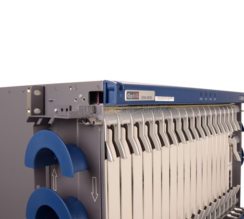
Should the nominal gain of the OAU1 board in the OSN 6800 be re-set after the type of the DCM between TDC and RDC is changed?

Product

OptiX OSN 6800

OptiX OSN 3800

Fault Type

DCM Module

Symptom

In a OptiX OSN 6800 40-channel project, the TN11OAU101 (gain ranges from 20 dB to 31 dB and the per-channel standard output optical power is +4 dBm) is used. In the initial stage, no DCM is configured between optical interface TDC and RDC of the OAU1. The nominal gain of the OAU1 is set to 20 dB on the T2000 and the per-channel input/output optical power is -16 dBm/+4 dBm. In later stages, a DCM(B) (it compensates for 40 km dispersion and the insertion loss is 5 dB) is added between TDC and RDC of the OAU1 because of dispersion issues. In this case, engineers are wondering if the nominal gain of the OAU1 should be re-set on the T2000, so that the per-channel output optical power of the board remains +4 dBm? Or the OAU1 adjusts the gain automatically to ensure that the per-channel output optical power remains +4 dBm?

Cause Analysis

None.

Procedure

  1. Check if the DCM insertion loss meets the requirement before replacing the DCM.
  2. Allowable DCM insertion loss = Gain of the OAU1 – Nominal gain (the setting on the T2000) If the insertion loss between TDC and RDC is very large and exceeds the adjustment range of the OAU1, the OAU1 reports the VOA_ADJUST_FAIL, which is a minor alarm. In this case, check if the fiber insertion loss is very large. If it is very large, remove the fiber faults.
  3. If the DCM insertion loss meets the requirements and the fiber faults are removed, engineers do not need to re-set the nominal gain on the T2000. The OAU1 adopts the automatic gain control (AGC) mode. The OAU1 monitors the output and input optical power in real time, so that the gain (the difference between the input and output optical power) of the OAU1 keeps the same as the value set on the T2000. Whether TDC and RDC interfaces are connected directly through a fiber jumper or a DCM is added between them, the per-channel input/output optical power is always -16 dBm/+4 dBm and the gain remains 20 dB.

Reference Information

None.

How Can I Obtain the Serial Number of a Fixed Switch?

04-Front_right 30°down 15°

How Can I Obtain the Serial Number of a Fixed Switch?

Log in to the switch through Telnet or the console interface, and then run the display elabel slot slot-id command (slot-id specifies the slot ID of the switch) in the user view to view electronic label information. In the command output, the BarCode field indicates the serial number of the switch.

<Quidway> display elabel slot 0
/$[System Integration Version]  
/$SystemIntegrationVersion=3.0   
      
      
[Slot_0]      
/$[Board Integration Version]  
/$BoardIntegrationVersion=3.0  
    
    
[Main_Board]    
      
/$[ArchivesInfo Version]      
/$ArchivesInfoVersion=3.0       
                 
           
[Board Properties]   
BoardType=CX22EFGEA      
BarCode=2102351820109C000451 
Item=02351820 
……………

NE ESC Communication Interrupted Because of the Closure of the OTU Laser

NE ESC communication interrupted because of the closure of the OTU laser.

Fault Type

NE Offline

ECC

Optical Transponder Unit

Symptom

An OptiX Metro 6100 NE at a station is unreachable by the NMS and cannot be manually logged in to. The ESC communication is interrupted and the NMS reports the NE_COMMU_BREAK and NE_NOT_LOGIN alarms.

Cause Analysis

The OptiX Metro 6100 and OptiX BWS 1600G support two types of supervisory channel: optical supervisory channel (OSC) and electrical supervisory channel (ESC). The ESC is transmitted by any OTU. The difference between the OSC and the ESC is that the OSC is transmitted by a dedicated supervisory channel board but the ESC is transmitted by the DCC byte or subcarrier module of the OTU.

When the ESC is used for communication, in the case that only the OTUs are used for connection of two NEs, when the ALS function is enabled or the lasers on the OTUs are turned off forcibly, the communication on the remote NE is interrupted, and users cannot log in to the NE.

Procedure

  1. Analyze the engineering document of the network and query the ECC routing table. It is confirmed that the ESC communication is used for the upstream and downstream NEs of the unreachable NE.
  2. It is confirmed that the lasers on an OTU board on the upstream peer NE are manually turned off for engineering purposes.
  3. An engineer must go to the station and turn on the lasers on the OTUs to restore the communication.

Reference Information

It is not recommended to use the ESC when two NEs are connected through the OTUs.

If the ESC is used for communication, engineers must turn on the lasers of the OTUs forcibly and it is recommended to set Automatic Laser Shutdown to Disabled (Automatic Laser Shutdown for some OTU boards is set to Enabled by default).


More related:

How to Configure the SIP-based Voice Service

GPON FTTH PPPoE login gets disconnected

How to Login Huawei Equipment Through the Local Serial Port